
Time Required to complete: 5 - 10 min.
Category: Modeling / Rigging
Hello and welcome to another 3D Studio Max Tutorial.
Today we will learn how to create and rig gears inside 3Ds MAX to create fluid animations as the one below:

So let's get started.
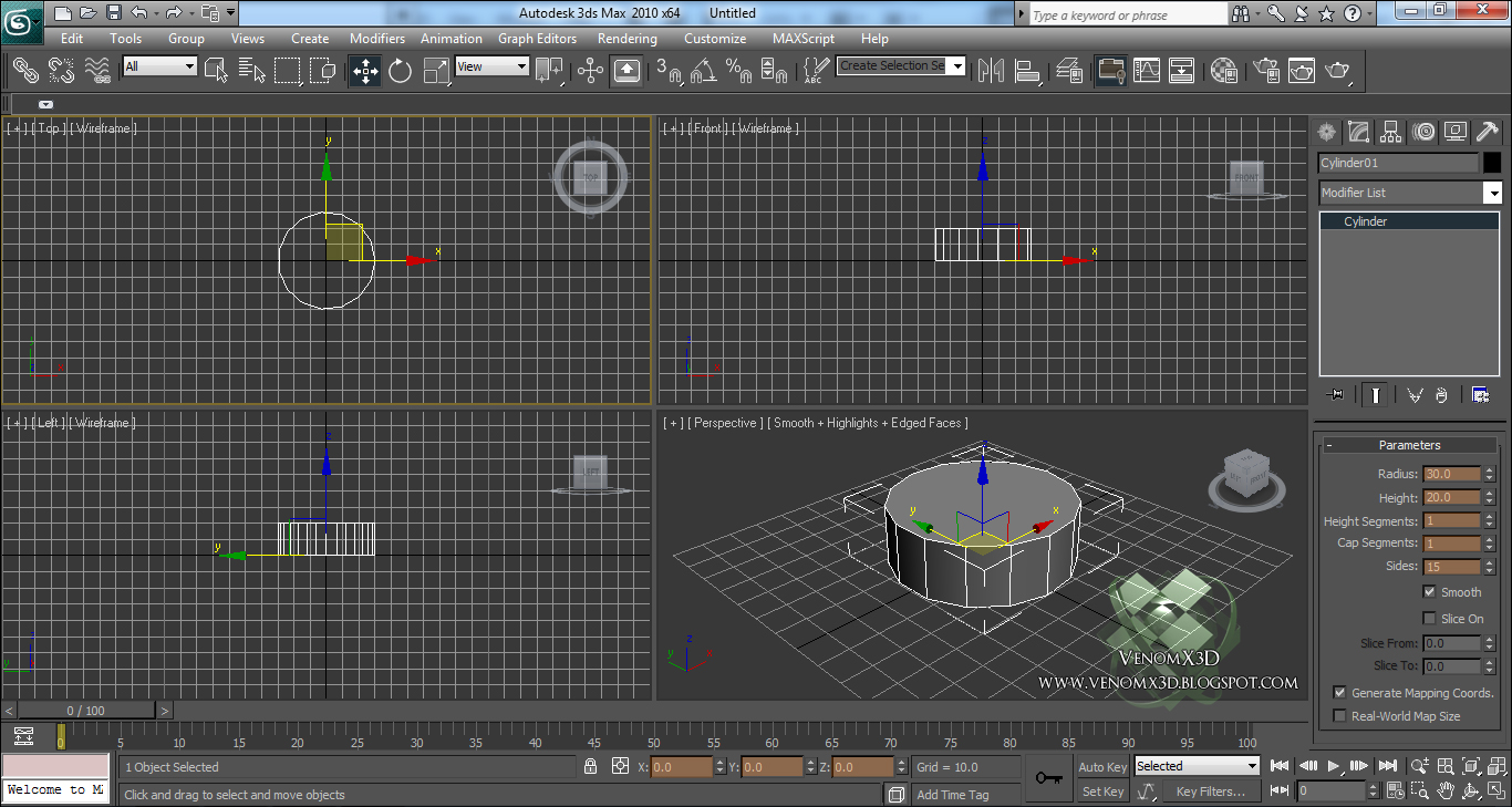
Step 1: Open 3Ds MAX and Create a Cylinder in the Top View then modify the following parameters:
Radius: 30
Height: 20
Height Segments: 1
Cap Segments: 1
Sides: 15
Step 2: Add an Edit Poly modifier on top of the Cylinder:

Step 3: Select all the Side Polygons (all except the top & bottom polys) and press on Inset Settings:
Inset Type: By Polygon
Size: 3.2

Step 4: With these polygons still selected hit Extrude Settings and choose a value of 4, then press OK.

Step 5: With the polygons still selected hit Bevel Settings. For Height choose 4 and for Outline Ammount -1, then press OK.

Step 6: Inside the Front View by using the selection tool (Q) select all the Vertices that create the top part of our gear:

Step 7: With these Vertices selected hit Z right next to Make Planar:

Step 8: Now select the Vertices that create the bottom part and then hit Z right next to Make Planar. You should end up with a planar gear as the one below:

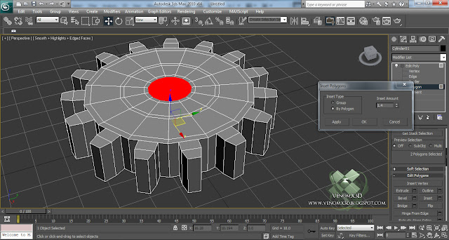
Step 9: Now go to Polygon Selection and select the Top & Bottom polys of our gear and hit Inset Settings > Inset Ammount : 2, hit Apply:

Step 10: Next change the Inset Ammount to 10. Hit Apply:

Step 11: Inset by a value of 1.4:

Step 12: Inset again by a value of 7:

Step 13: And for the last time by a value of 1.4:
Step 14: With the Inner Polygons still selected hit Bridge Settings > OK:

Step 15: Select the polygons as you can see in the image . Make sure you select them on bottom as well!

Step 16: Extrude these polygons by a value of 2:

Step 17: Now select the following polys as you can see in the image below. Make sure that you select them on the opposite part as well!

Step 18: Press on Bridge to end up with something like this:

Step 19: We're done with the modeling. Now with the Move Tool (W) selected, by holding Shift, Clone the gear as a Copy:

Step 20: Right Click on any of the gears > Wire Parameters > Transform > Rotation > Z Rotation then click on the other gear:

For the second gear select Transform > Rotation > Z Rotation as well:

Step 21: The Wire Parameters dialog should pop-up. Make sure that you click on the <---> icon, press on Connect and modify one of the Z_Rotation to -Z_Rotation as you can see below:

Now if you use the Rotate Tool and you start rotating one gear on the Z Axis you will see that the other one is rotating too, in the opposite direction, like they're interacting with each other. Also there is a problem if you want to make a loopable animation, that we solve in the next step:
Step 22: With one gear selected , inside any Viewport Right Click and go to Curve Editor. Inside the Curve Editor, select Rotation > Z Rotation > Z_Rotation and select both points, then press on Set Tangents to Liniar. This should make a straight line from frame 0 to your last frame. Now your animation should be constant, that means there's no delay when the gear starts or stops rotating.

With the same technique you can achieve results like these:

For any question about this tutorial please use the comment section below.
Thanks for watching and I hope this helped :)
See you next time !
Hit like on www.facebook.com/VenomX3D to keep in touch with the newest tutorials!